
ASME B18.5 80°Slotted Countersunk Head Screws
ASME/ANSI B18.5 80° slotted countersunk head screws feature an 80° countersunk head and a traditional slotted drive for flush, low-profile fastening. The angled head seats into a matching countersunk hole, allowing the fastener head to remain close to or below the surrounding surface and reducing interference with adjacent components.
The slotted drive provides a simple, accessible driving interface, while the countersunk head helps create a clean fastening surface. This configuration is suitable for fixtures, fabricated assemblies, equipment panels, brackets, and other applications where a recessed fastener head is required. For selection, customers should consider the nominal diameter, screw length, head dimensions, countersink angle, material, mechanical property requirements, and surface finish. Carbon steel, alloy steel, stainless steel, and nonferrous versions can be specified according to the applicable material and performance requirements.


Specification:
| Item | Specification |
|---|---|
| Specification | ASME/ANSI B18.5 |
| Product Type | Slotted Countersunk Head Screw |
| Head Angle | 80° |
| Drive Type | Slotted |
| Thread System | Inch |
| Thread Series | UNC/UNF |
| Size Range | 1/4”-1-1/2“ |
| Steel Property | SAE J429 |
| Stainless Steel | ASTM F593 |
| Material | Carbon Steel, Stainless Steel, Brass |
| Surface Treatment | Zinc Plated,Black Oxidation,Dacromet, Bright Finish,Passivation |
- RELATED SCREW LISTS:
- Cross Recess Countersunk Screw
- DIN965 Cross Recess Countersunk Screw
- Cross Recess Pan Head Screw
- DIN7985 Cross Recess Pan Head Screw
- ASME B18.6.3 Phillips Pan Head Screw
- Slotted Countersunk Screw
- DIN963 Slotted Countersunk Screw
- Slotted Pan Head Screw
- DIN85 Slotted Pan Head Screw
- ASME B18.6.3 Slotted Pan Head Screw
- DIN 967 Cross Recessed Pan Head Screws
- DIN966 Cross Recessed Raised Screws
Dimension Chart:
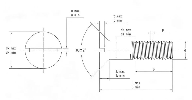
| Thread Diameter | 1/4 | 5/16 | 3/8 | 7/16 | 1/2 | 5/8 | 3/4 | 7/8 | 1 | 1-1/8 | 1-1/4 | 1-3/8 | 1-1/2 |
| P | 20|28|32 | 18|24|32 | 16|24|32 | 14|20|28 | 13|20|28 | 11|18|24 | 10|16|20 | 9|14|20 | 8|12|20 | 7|12|18 | 7|12|18 | 12|18 | 6|12|18 |
| ds max | 0.26 | 0.324 | 0.388 | 0.452 | 0.515 | 0.642 | 0.768 | 0.895 | 1.022 | 1.149 | 1.277 | 1.404 | 1.531 |
| ds min | 0.237 | 0.298 | 0.36 | 0.421 | 0.483 | 0.605 | 0.729 | 0.852 | 0.976 | 1.098 | 1.223 | 1.345 | 1.47 |
| dk max | 0.493 | 0.618 | 0.74 | 0.803 | 0.935 | 1.169 | 1.402 | 1.637 | 1.869 | 2.104 | 2.337 | 2.571 | 2.804 |
| dk min | 0.445 | 0.558 | 0.668 | 0.726 | 0.845 | 1.066 | 1.285 | 1.511 | 1.735 | 1.962 | 2.187 | 2.414 | 2.64 |
| k max | 0.15 | 0.189 | 0.225 | 0.226 | 0.269 | 0.336 | 0.403 | 0.47 | 0.537 | 0.604 | 0.671 | 0.738 | 0.805 |
| k min | 0.131 | 0.164 | 0.196 | 0.196 | 0.233 | 0.292 | 0.349 | 0.408 | 0.466 | 0.525 | 0.582 | 0.641 | 0.698 |
| n max | 0.075 | 0.084 | 0.094 | 0.094 | 0.106 | 0.133 | 0.149 | 0.167 | 0.188 | 0.196 | 0.211 | 0.226 | 0.258 |
| n min | 0.064 | 0.072 | 0.081 | 0.081 | 0.091 | 0.116 | 0.131 | 0.147 | 0.166 | 0.178 | 0.193 | 0.208 | 0.24 |
| t max | 0.068 | 0.086 | 0.103 | 0.103 | 0.103 | 0.137 | 0.171 | 0.206 | 0.24 | 0.257 | 0.291 | 0.326 | 0.36 |
| t min | 0.045 | 0.057 | 0.068 | 0.068 | 0.068 | 0.091 | 0.115 | 0.138 | 0.162 | 0.173 | 0.197 | 0.22 | 0.244 |
Mechanical Property:
SAE J429 – Carbon Steel
Carbon steel 80° slotted countersunk head screws can be supplied with mechanical properties according to applicable SAE J429 grades. This specification establishes mechanical and quality requirements for externally threaded steel fasteners, including tensile strength, proof load, and hardness. Available strength grades are selected according to product dimensions and application requirements.
ASTM F593 – Stainless Steel
Stainless steel 80° slotted countersunk head screws can be supplied in Type 304 (18-8) and Type 316 stainless steel. ASTM F593 specifies the chemical composition and mechanical property requirements for stainless steel fasteners, including tensile strength, yield strength, and hardness. Applicable alloy groups and conditions are selected according to the required material and strength specifications.